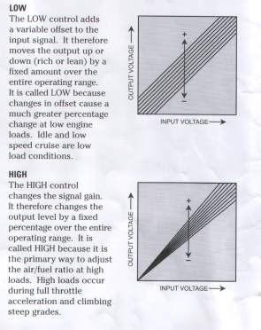
 Applicable
on normally aspirated engines and on turbo engines
Applicable
on normally aspirated engines and on turbo engines
Most of the fuel injected engines
suffer a common problem: they run lean under full load operation. If we
attempt to obtain a more adequate mixture, usually we have an over rich
idle. Replacing the original device with our "RISING RATE"
regulator, will supply more fuel at the top-end, without causing an
overrich mixture at the lower/power range.Resulting in quicker
accelleration and throttle response without affecting your gas
mileage.Overcomes flat spots, eliminates loss of power, up-to 18% of
power increase if installed together with Pipercross Induction
High Performance Filter and Torque Master Ultra Performance Spark Plugs.
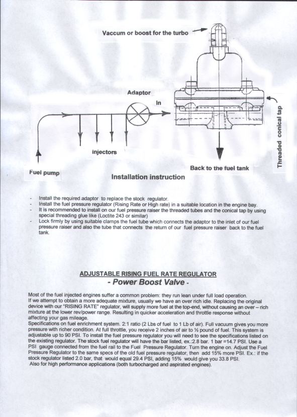
More information on How To install our Special
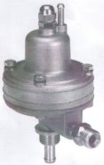
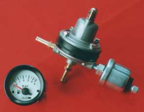
POWER BOOST VALVE
- Before disconnecting the stock fuel pressure regulator you should
measure the stock pressure at idle (usually it is about 2,5bar).
Install our adaptor in the hole left by the removal of the stock
fuel
pressure regulator.
Install our Fuel Pressure Valve in the engine bay (not too far from
where it was the stock fuel pressure regulator) by using the fixing
plate with
the two holes.
Connect (by using a suitable fuel tubing) our adaptor to one
of the
two horizontal outlet holes of our POWER BOOST valve with the
threaded
connections supplied.Close the outlet hole remained opened by using
the supplied conical tap.Lock firmly by putting LOCTITE 243 or
similar on
threadings and clamps.
Connect the stock fuel return tube to tank to the lower
vertical
connection of our POWER BOOST valve.Lock firmly by putting LOCTITE
243 or similar
on threadings and clamp.If stock return is from fuel rail close the
hole remained opened by putting a suitable cover tap.
Connect the stock 5mm diameter vacuum tube to the upper
connection of
our POWER BOOST valve.
Install a fuel pressure gauge between our adaptor and our
POWER BOOST
valve by using a "T" connection.
Unscrew the bolt located close to the vacuum tubing and loosen the
lower nut.Switch on the engine and and keep it at idle.Set our POWER
BOOST
valve (by using the setting screw) at about 10% more of the
idle stock fuel
pressure.For example from 2,5 bar to 2,7/2,8 bar.
Tight nut and bolt and remove fuel pressure gauge.
Our POWER BOOST valve is now ready to give you automatically a
stronge fuel pressure for much better Torque and Acceleration.
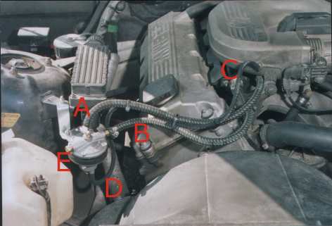 |
Example of installation
"POWER BOOST Valve " on BMW.The valve was installed
up-side down due to restricted space for the tubings.
A= Return to fuel tank.
B= Outlet to be connected to our adaptor.
C= Adaptor.
D= Vacuum tube.
E= Conical tap or connection for our pressure sensor. |
| Original return fuel tank
connection located on the rail was closed by a tap. |
MORE POWER GUARANTEED! |
 |
Electronic Fuel Pressure
Meter.
Very
Usefull and precise for Perfect
/Customized engine Tuning .Very
safe as there is no fuel going inside the car like with mechanical
meters.It also allows the driver to detect possible
malfuctions on fuels pressure line.Very Easy to connect.Is is
composed of a Pressure Sensor to be screwed into our Fuel Pressure
Regulator "POWER BOOST" and an Electronic Fuel
pressure Meter to be installed inside the car.
Very
Easy to install- Instructions Included |
|
MAKE YOUR PERSONAL AIR/FUEL
ADJUSTMENTS AND GAIN UP TO 20% OF ENGINE POWER - NEW FOR
U.S.A. Easy to install -Instructions
Included |
 |
The module provides precise
adjustment of Air/Fuel Calibrator Ratio over the entire operating
range of an internal combustion engine. It is especially useful to
achieve maximum power from your engine or for re-calibration of
modified engines.The module gives the user a conveniente way to
set A/F ratio for rich, lean or stechiometric operation over the
entire RPM and load range.IT provides a means to achieve a best
fit straight line of approximation to the desired Air/fel
calibration curve.It gives the user the ability to make these
adjustments without riprogramming the ECU.Furthermore, these
adjustments can be made by the driver on-the-fly to optimize the
Air/fuel Ratio for the current driving situation. |
Special consideration has gone into the ARC1-003 to make sure that
the car operates like stock in most modes of operation.The benefit of
stock operation are stock drivability,cold start,fuel economy and
emissions.The most important benefit is that the ECU will not adapt to
the changes made by the high knob.The ARC1-003 is designed to only alter
the fuel curve at high engine loads where fuel adaptation does not
occur.Therefore, the changes made will be permanent and will not result
in a check engine light.The ARC1-003 does not directly affect the
ignition timing curve. Most performance chips make more power by
advancing the ignition timing.However, this is dangerous because on a
hot day climbing a hill,you could wind up with too much advance and
cause detonation in the motor.
Very important and usefull also on those engines with ECU
modification but with other subsequent engine modifications.Normally you
should modify the ECU again according to the added engine modifications
made.By using the ARC1-003 you can change the Air/fuel ratio and adjust
the fuel mixture by yourself at all times making the engine operating
the best possible way in order to have the maximum increase of power
with less fuel consuption and the lowest possible exhaust emmissions.
Air/fuel Ratio Calibrator
ARC1-003
Description:
The ARC1-003 Air/fuel Ratio Calibrator provides precise adjustment of air/fuel (A/F) ratio over the upper load range of an internal combustion engine. It is designed specifically for naturally aspirated engines with mild performance enhancements. The ARC1-003 follows the stock fuel curve over the light load range which minimizes adaptation on modern closed loop engine management systems. At higher loads, the fuel curve can be made more rich or lean to optimize engine performance.
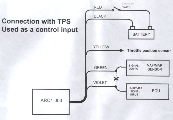
The LOW control of the ARC1-003 sets the threshold at which alteration of the fuel curve begins. The HIGH control sets the degree to which the fuel mixture is made more rich or lean. A provision on the ARC1-003 allows the modification to the fuel curve to be dependant on an external control input such as MAP or TPS.
The ARC1 is typically used in conjunction with a precision air/fuel ratio meter such as the Split Second ARM1. The air/fuel ratio meter provides the required information needed to properly set the ARC1 front panel controls.
The ARC1-003 is part of the ARC1 family. Several versions are available which are optimized for different applications. The standard ARC1 provides gain and offset calibration and is well suited for general purpose engine calibration. The ARC1-002 is tailored for engines that have been converted to forced induction. It provides compensation for larger injectors and adjustable enrichment in the boost
region.
 |
Features:
� Low control sets modification threshold
� High control sets degree of rich or lean operation in high load range
� Optional external control input
� +5V regulated output available for MAP sensor reference voltage
� Transient surge and battery reversal protection Wire
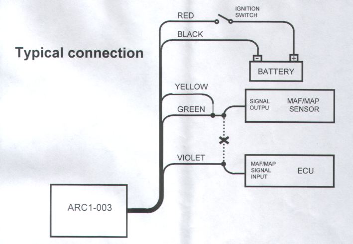
Assignments:
LABEL CONNECT TO WIRE COLOR
BATT+ Battery positive (+12V) Red
BATT- Battery negative (chassis ground) Black
SIGI+ MAF/MAP sensor signal output Green
VC Green wire (optional connection to TPS) Yellow
SIGO ECU signal input (MAF or MAP input) Violet
|
Front Panel Adjustments:
LOW
The LOW control sets the point at which change to the fuel curve begins to occur. The threshold is based on the voltage on the yellow wire. The threshold point can be varied from 1V to 3V. If the yellow and green wires are tied together, the threshold is based on the input voltage.
HIGH
The HIGH control adjusts the degree to which the stock fuel curve is made more rich or lean above the threshold point. The amount of change to the fuel mixture is a function of the HIGH setting and how far above the threshold VC (the control voltage on the yellow wire) is.
Adjustment Procedure:
Begin with the low and high controls set to the zero position. At these settings, the output voltage matches the input. Use a precision air/fuel ratio meter
to monitor the operating fuel mixture.
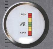 |
Ask for the price of our Digital Air/Fuel
meter.Very precise and clear, it allows you to
monitor the engine fuel mixture in all situations.
For the best engine performance and to save your engine from
damages due a too lean mixture.Applicable on normally
aspirated engines and on turbo engines.Especially
on Turbo modyfied engines our Digital Air/Fuel Indicator
is extremely important to avoid engine breakages which
might cost high amount of money to repair.Very
easy to connect - instructions included. |
Adjust the HIGH knob to the plus side to make the top end fuel mixture more rich. Adjust to the minus side to lean out the top end fuel mixture. The amount of change is a function of both the HIGH setting and how far above the threshold VC (the control voltage) is. For a similar amount of top end enrichment, if the threshold is increased, the HIGH setting must also be increased.
The LOW knob can be adjusted in order to change the threshold where change to the fuel mixture begins to occur. If the threshold is moved down, there is a risk of changes being picked up by the ECU and activating adaptation. Adaptation works to reduce the effect of fuel mixture changes made with the ARC1-003. If changes made through the ARC1-003 are negated by the ECU over time, the LOW setting needs to be increased so that the area of the fuel curve that is altered is above the primary adaptation area.
 |
 |
Electrical Characteristics:
PARAMETER CONDITIONS MIN TYP MAX UNITS
Low Range VC to BATT- 1 3 V
High Range % adjust of full scale range -20 +20 %
Supply Voltage BATT+ to BATT- 12 13.5 16 V
Input Voltage SIGI to BATT- 0 5 V
Output Voltage SIGO to BATT- 0 5 V
Input Resistance SIGI to BATT- 100 kW
Output Resistance SIGO to BATT- 100 W
Output Current +5V output 500 mA
Supply Current BATT+ terminal 20 mA